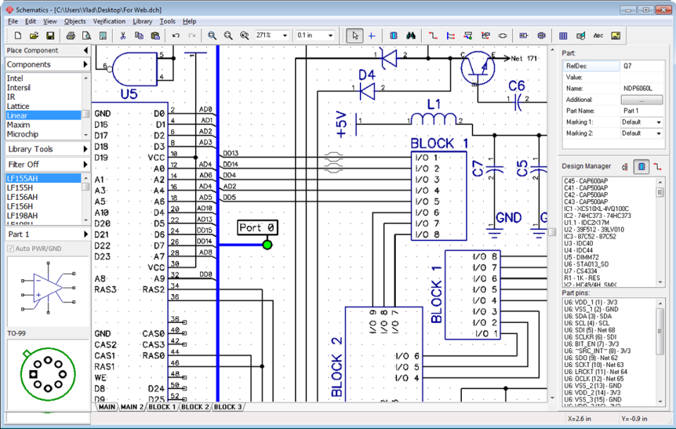
DRC same net clearance check (Trace to Trace, SMD to Pad, SMD to Via. To add a schematic sheet to a current file is easy. However some new tricks have been added too: 1. I Use DipTrace, and I use their forum, and yes it is painfully slow, usually a couple of days before a reply so I can understand your frustration, and even after I spent over 800.00 on a license, when you call tech support they tell you to post a topic and hang up on you.

Free version limited to 300 pads and 2 layers. Just posted on the forum from DT Team: We have published new version 3.2 today, the major thing we changed in it is polishing of existing features (added in 3.0 and 3.1).
Diptrace forum full#
Diptrace forum software#
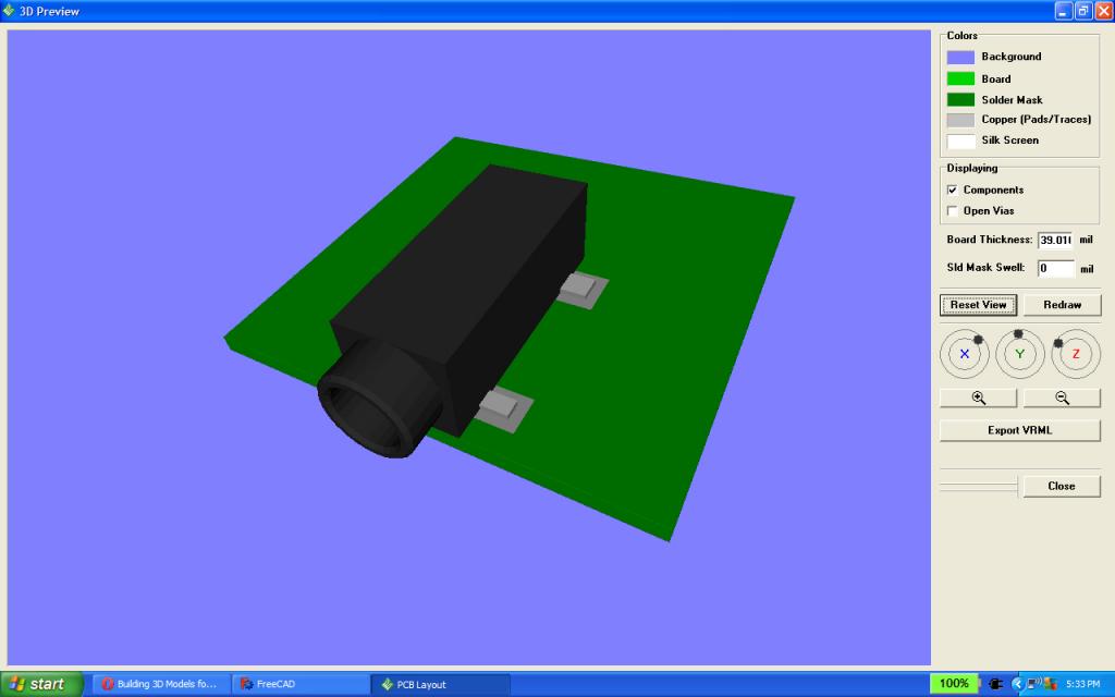
Twelve! Even if you counted the individual gates, you don't get twelve. DipTrace is an advanced PCB design software application that consists of 4 modules: PCB Layout with shape-based autorouter, high-speed/differential signal routing tools, and 3D PCB Preview/Export, Schematic Capture, and Component/Pattern Editors that allow you to design custom component/footprint libraries. The PCD DipTrace produced had twelve chips. DipTrace Schematic Capture, Drawing Schematics, Hierarchical Design, BOM, Exporting net-lists, etc. Voili! It appears DipTrace doesn't like two components connecting directly together you have to draw a line between the terminus points for the program to understand what you want.Īm I crazy? Has anyone else had this problem? Lets assume there is no connection I separated the components and connected them with a short trace. I was convinced I couldn't see any other errors! Then I changed my perspective. As far as I know, Proteus does not simulate key switch bounce. The second is you said you are simulating on Proteus.

Debouncing a key switch is about the most basic necessity of any embedded system that uses switches as inputs. I could see a gap between my connections! You said you wrote your program without consideration for debounce. Im already seeing where I want to venture off into Fusion 360 soon for my CAM work, but this is.
Diptrace forum drivers#
When, in the File menu, the Convert to PCB option is clicked DipTrace returns: 'Components B1 and VO1 don't have patterns. The drivers for the USB connection, the Control software for the machine, and the web-based CAM software all worked together first shot. Have drawn a schematic attached herewith. AAEON is taking pre-orders for the UP Square 2 starting at 161 for the model with a Celeron N6210, 2GB RAM, 32GB eMMC flash, and going up to 323 with a Pentium J6426 CPU, 64GB eMMC flash, and 16GB RAM. I lucked upon it, since there were so many errors. Hello DipTrace Forum, Have created dozens of PCB using the PCB Layout tool but have not created a PCB by converting a schematic to a PCB. With TPM v2.0 on board, UP Squared V2 has added hardware-based, security-related functions as well. It started with na easy one, once I found on. Consolidated Leo OGR Forum Member, Oh man DipTrace has more dialog boxes than you can shake a stick at. I did eventually learn if you double clicked the error,something became highlighted in red, but it took me a little while longer to find the problem. And being unfamiliar with the notation, it took me a while to grok even where an error occurred. I was shocked to see a two page error list.
Diptrace forum verification#
what got me was trying to use the verification tool. I had unwanted traces all over my schematic. We can dismiss the vagaries of the UI I'll never figure out why it keeps switching into draw connector mode on ts own. I felt like a Windows person trying to learn Linux. Spent my Sunday afternoon trying to learn DipTrace. Importing a DXF into DipTrace is a little tricky because the user interface is not self-explanatory in any way.


 0 kommentar(er)
